Thinning Shear Anatomy
Name the tooth features before comparing their designs.
By JapanShears EditorialUpdated
On this page
Look beyond the number in a thinner’s title. The useful next questions are where the teeth sit, how wide their bodies and gaps are, and what happens at each tip. Those features give you something concrete to compare when two tools share a count.
Follow the two blades
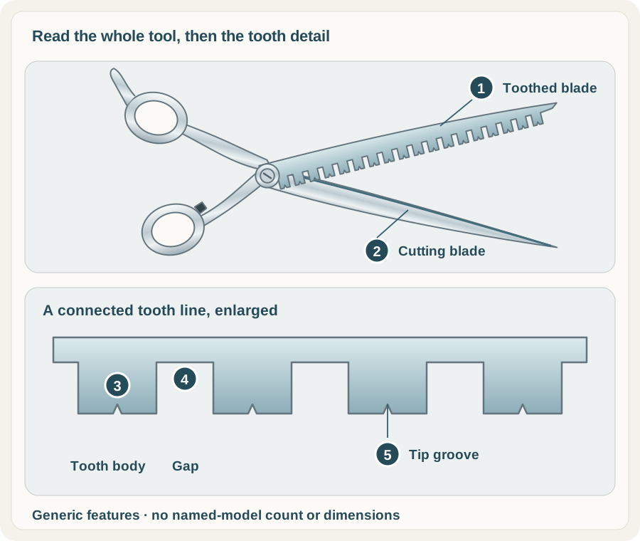
A typical thinner pairs a toothed blade with an opposing continuous cutting blade. Follow each complete half through the pivot to its handle. The rings and shanks help you read the whole tool; a close-up of the teeth answers a different question.
 Open illustration at full size
 - Toothed bladeThe blade carrying the row of teeth. Look at the complete layout as well as the count.
- Cutting bladeThe opposing continuous blade closes against the toothed construction.
- Tooth bodyThe metal projection joined to the blade’s continuous base. Width and shape are separate from count.
- GapThe space between adjacent tooth bodies. Compare its shape and spacing.
- Tip grooveA feature at this illustrative tooth tip. Other models may use different grooves or a flat tip.
The enlarged strip shows one possible grooved tip. A tooth body is the metal projection joined to the blade’s base; a gap is the space between neighbouring bodies. A tip groove is a feature at the end of a tooth. Models can change all three while keeping the same tooth count.
Grooves also differ. Joewell describes small tooth-tip grooves on SNT-40, while its official catalogue describes flat teeth for JGC-12’s cut-and-thin design. The generic drawing is a way to name the parts, rather than a pattern shared by every thinner.
Keep tooth form and blade terms separate
A flat tooth description concerns the tooth. Convex, semi-convex and a maker’s named blade term concern other parts of the construction; do not treat them as interchangeable labels. The blade vocabulary guide separates edge grind, blade profile and cutting-line shape.
Count is separate from length too. A nominal six-inch label describes the maker’s whole-tool size convention. It does not establish a six-inch toothed span. Use a published blade measurement when that comparison matters.
Read a real tool in two views
Start with a complete photograph for handle layout, pivot and the position of the toothed blade. Then use a clear tooth-line view to examine bodies, gaps and tips. A small thumbnail can hide the very feature you are trying to compare.
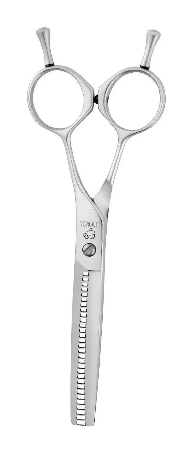
The E-30 listing gives you a specific 30-tooth, nominal 5.6-inch comparison with a symmetrical handle. Its maker reference names the Standard JOEWELL Blade and states the model’s cut ratio. We use the photograph to see the tool and the specification to identify it.
Neither the ring shape nor the side carrying the teeth establishes cutting hand by itself. Some maker references distinguish original and reverse tooth-blade positions. Keep that orientation separate from a confirmed left- or right-handed build; the handedness guide explains the difference.
Turn the landmarks into a comparison
Write down the hand, nominal size, handle, tooth count and named tip or blade features. Then compare the maker’s cut-rate statement alongside them. Our same-count examples show why that extra reading matters for actual 30- and 40-tooth models.
Use the thinner buying guide to give the tool a role. If you are learning that role, take it into a supervised observation brief. Catching, folding or a changed closing action calls for the care and service guide, rather than a guess about the tooth pattern.